

Bare Metal STM32 - UART
UART Protocol
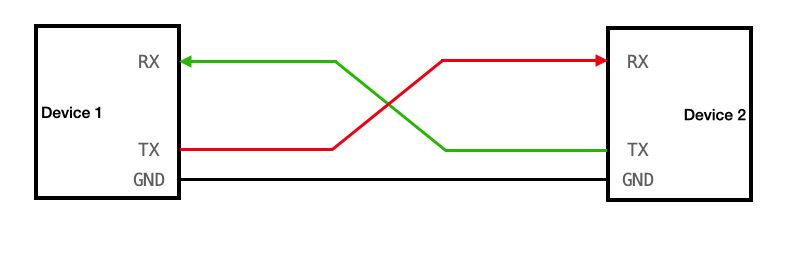
UART (Universal Asynchronous Receiver-Transmitter) is a a two-wire protocol for async (i.e. no clock is required) serial communication. Two devices communicate with each of their TX (Transmit) lines connected to the other’s RX (Receive).
UART Modes

- Simplex: Data tx/rx in one direction
- Half Duplex: Data tx/rx in either direction, but takes turns
- Full Duplex: Data tx/rx in either direction, simultaneously
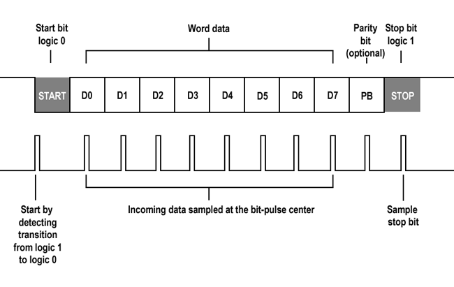
Protocol Summary
- Start bit: Always
0 - Data: 5-9 bits
- Parity bit: for error checking
- Stop bit: Either
1or11
Baud Rate: Connection speed expressed in bits per second (bps)
TX Driver
Configure GPIO Pins
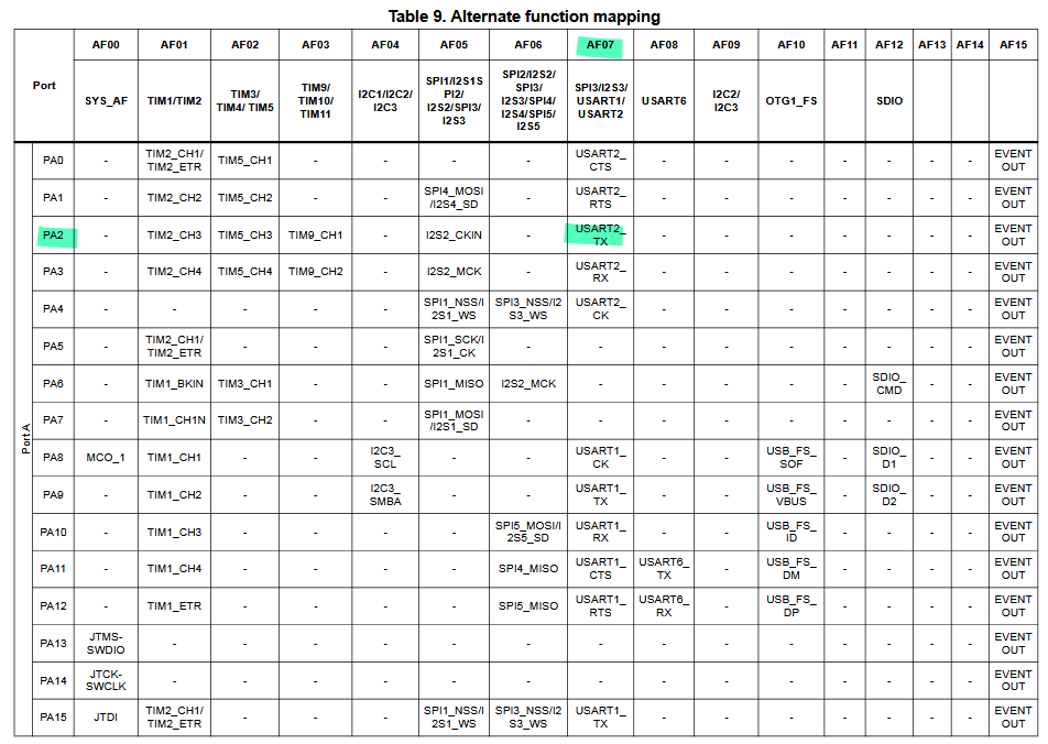
The STM32 datasheet refers UART as USART2 (S being synchronous). In order to use it, the pin must be configured in Alternate Function mode. The datasheet has a table that indicates that in order to use USART2_TX we must configurePA2 with AF07.
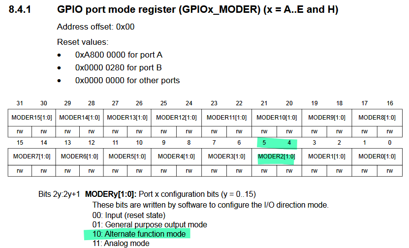
In the Reference Manual, we know from before that we can set a GPIO pin mode as follows:
#define GPIOAEN (1U<<0)
// Enable clock access to GPIOARCC->AHB1ENR |= GPIOAEN;
// Set to PA2 mode to alternate function mode (10 - AF mode)GPIOA->MODER |= (1<<5);GPIOA->MODER &= ~(1<<4);
Once we set the PA2 to AF Mode, we should also specify what the alternate function is. In the Reference Manual, there exist two 32 bit registers that help set the values for each pin:
- AFRL (Alternate Function Register Low): handles pins 0-7
- AFRH (Alternate Function Register High): handles pins 8-15
We are working with PA2 so we look at AFRL (indicated by AFR[0] in the code). AF7 should be set to 0111.
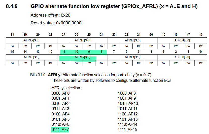
// Set PA2 Alternate type to UART_TX (AF07) (0111 - AF7)GPIOA->AFR[0] &= ~(1U<<11);GPIOA->AFR[0] |= (1U<<10);GPIOA->AFR[0] |= (1U<<9);GPIOA->AFR[0] |= (1U<<8);Configuring UART module
Just like how we gave clock access to GPIOA, we must do the same to the UART peripheral. The datasheet shows the block diagram where the USART2 peripheral is connected to the APB1 bus:
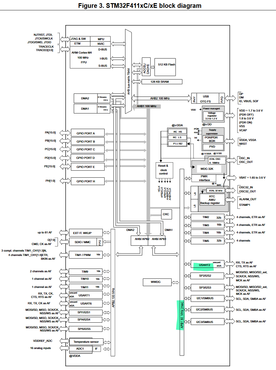
We can then look in the Reference Manual to find the enable register at section 6.3.11. UART enable is at bit 17.
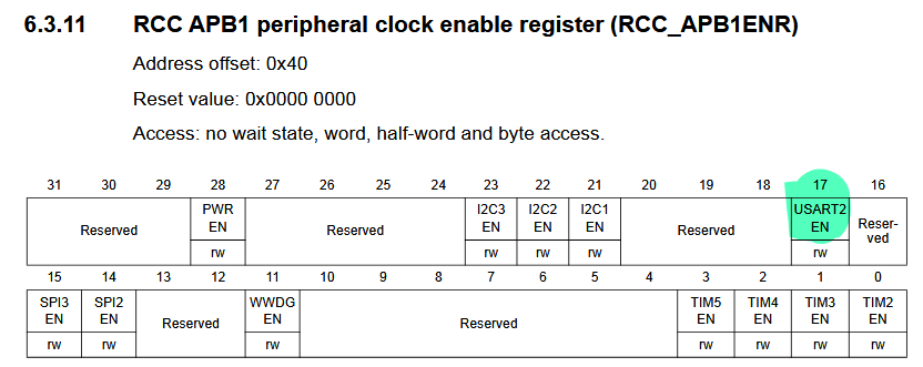
#define UART2EN (1U<<17)
// Enable clock access to UART2RCC->APB1ENR |= UART2EN;
Setting The Baud Rate
The Baud rate is set by modifying the Baud Rate Register. We need a value called USARTDIV that is a floating point value, where the bits are split into the Mantissa and Fraction part.
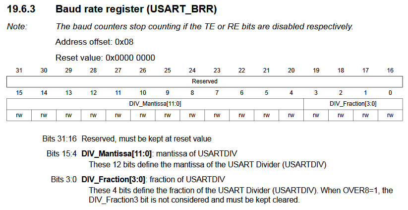
This value is obtained by re-arranging the equation found in section 19.3.4 of the Reference Manual:
Where:
- fCK is the peripheral clock source frequency used to generate the baud rate. This is set to
16MHz. - OVER8 is a single bit that defines oversampling amount. Defaults to
0.
Note: USART samples each bit multiple times to filter noise. With OVER8=0 (default) it samples 16 times per bit. With OVER8=1, it samples 8 times per bit (which is faster but more noisy).
Prescaler: A hardware divider that scales a clock speed to a slower frequency. USARTDIV is the prescaler, it divides the fCK (16M Hz) down to achieve the baud rate (~115,200 Hz).
Our desired baud rate is 115,200, so doing this calculation will return USARTDIV = 8.6875. We could have also just looked at Table 75 in the Reference Manual.
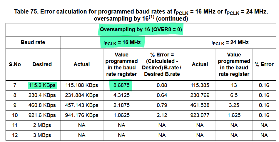
HOWEVER remember USARTDIV is the raw float value, and we must separate it into the Mantissa and Fraction to . We can do this by the formula given:
#define BRR_115200_16MHZ 0x8BU
// Configure the Baud RateUSART2->BRR = BRR_115200_16MHZ;
We also need to configure the USART Control Register 1 to:
- Enable Transmitter (bit 3)
- Enable USART (bit 13)
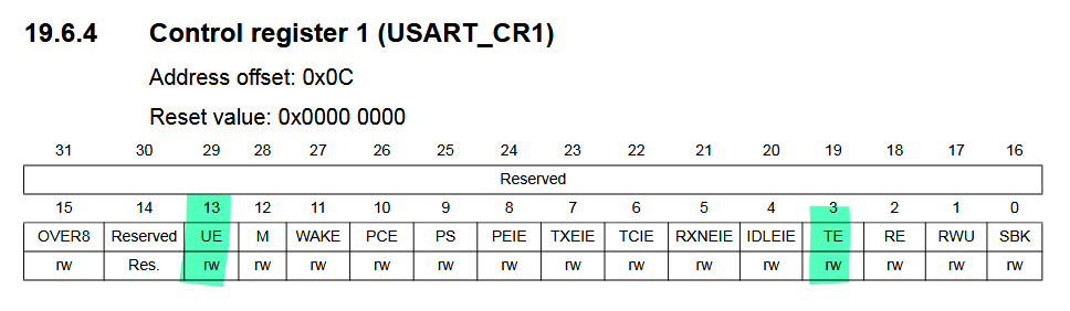
#define CR1_TE (1U<<3)#define CR1_UE (1U<<13)
// Configure transfer directionUSART2->CR1 = CR1_TE;
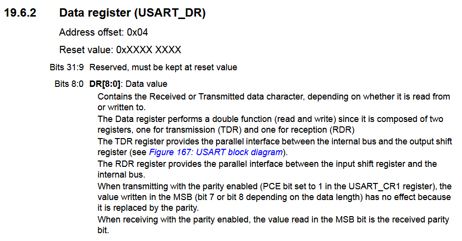
// Enable UART moduleUSART2->CR1 |= CR1_UE;Finally we can override the behaviour of printf to call a custom function for each character. This will first check if the status register (USART_SR) indicates that the transmit register is empty before writing to the data register (USART_DR).
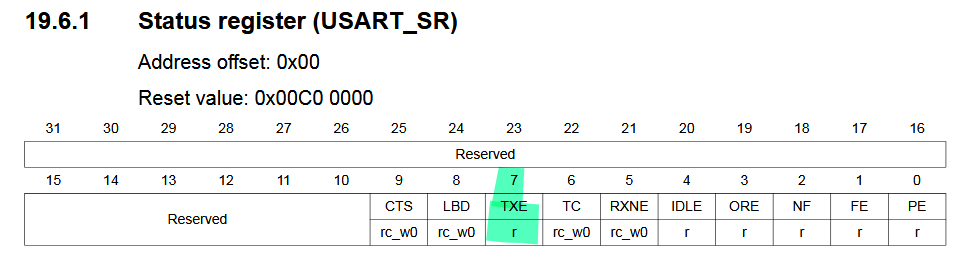
#define SR_TXE (1U<<7)
int __io_putchar(int ch){  uart2_write(ch);  return ch;}
void uart2_write(int ch){  // Make sure transmit data register is empty  while (!(USART2->SR & SR_TXE)){}
  // Write to transmit data register  USART2->DR = (ch & 0xFF);}
The final code will look like:
#include "uart.h"
int main(void){ uart2_tx_init(); while(1) { printf("The quick brown fox jumps over the lazy dog\n\r"); }}#ifndef UART_H_#define UART_H_
#include <stdint.h> // uint32_t#include "stm32f4xx.h"
void uart2_tx_init(void);
#endif /* UART_H_ */#include "uart.h"
#define GPIOAEN (1U<<0)#define UART2EN (1U<<17)
#define BRR_115200_16MHZ 0x8BU
#define CR1_TE (1U<<3)#define CR1_UE (1U<<13)#define SR_TXE (1U<<7)
void uart2_write(int chd);
int __io_putchar(int ch){ uart2_write(ch); return ch;}
void uart2_write(int ch){ // Make sure transmit data register is empty while (!(USART2->SR & SR_TXE)){}
// Write to transmit data register USART2->DR = (ch & 0xFF);
}
void uart2_tx_init(void){ // ------------ Configure UART GPIO Pins ------------ // Enable clock access to GPIOA RCC->AHB1ENR |= GPIOAEN;
// Set to PA2 mode to alternate function mode (10 - AF mode) GPIOA->MODER |= (1<<5); GPIOA->MODER &= ~(1<<4);
// Set PA2 Alternate type to UART_TX (AF07) (0111 - AF7) GPIOA->AFR[0] &= ~(1U<<11); GPIOA->AFR[0] |= (1U<<10); GPIOA->AFR[0] |= (1U<<9); GPIOA->AFR[0] |= (1U<<8);
// ------------ Configure UART module ------------ // Enable clock access to UART2 RCC->APB1ENR |= UART2EN;
// Configure UART baud rate USART2->BRR = BRR_115200_16MHZ;
// Configure transfer direction USART2->CR1 = CR1_TE;
// Enable UART module USART2->CR1 |= CR1_UE;}RX Driver
The RX driver is very simple. The following is a simple demo of reading from UART and using that data to light an LED (connected to PA5).
#include <stdio.h>
#include "uart.h"
#define GPIOAEN     (1U<<0)#define GPIOA5         (1U<<5)#define LED_PIN     GPIOA5
char key;
int main(void){
  // Enable clock access to GPIOA  RCC->AHB1ENR |= GPIOAEN;
  // Set to PA5 as output pin  GPIOA->MODER |= (1<<10);  GPIOA->MODER &= ~(1<<11);
  uart2_rxtx_init();
while(1) { key = uart2_read(); // turn on LED if we read `1`, turn off if we read '0' (key == '1') ? (GPIOA->ODR |= LED_PIN) : (GPIOA->ODR &= ~LED_PIN); }}#ifndef UART_H_#define UART_H_
#include <stdint.h> // uint32_t#include "stm32f4xx.h"
void uart2_tx_init(void);
#endif /* UART_H_ */#include "uart.h"
#define GPIOAEN (1U<<0)#define UART2EN (1U<<17)
#define BRR_115200_16MHZ 0x8BU
#define CR1_TE (1U<<3)#define CR1_RE (1U<<2)#define CR1_UE (1U<<13)
#define SR_TXE (1U<<7)#define SR_RXNE (1U<<5)
// ==================== RX ====================char uart2_read(void){ // Make sure receive data register is empty while (!(USART2->SR & SR_RXNE)){}
// Write to receive data register return USART2->DR;}
void uart2_rxtx_init(void){ // ------------ Configure UART GPIO Pins ------------ // Enable clock access to GPIOA RCC->AHB1ENR |= GPIOAEN;
// Set to PA2 mode to alternate function mode (10 - AF mode) GPIOA->MODER |= (1<<5); GPIOA->MODER &= ~(1<<4);
// Set PA2 Alternate type to UART_RX (AF07) (0111 - AF7) GPIOA->AFR[0] &= ~(1U<<11); GPIOA->AFR[0] |= (1U<<10); GPIOA->AFR[0] |= (1U<<9); GPIOA->AFR[0] |= (1U<<8);
// Set to PA3 mode to alternate function mode (10 - AF mode) GPIOA->MODER |= (1<<7); GPIOA->MODER &= ~(1<<6);
// Set PA3 Alternate type to UART_RX (AF07) (0111 - AF7) GPIOA->AFR[0] &= ~(1U<<15); GPIOA->AFR[0] |= (1U<<14); GPIOA->AFR[0] |= (1U<<13); GPIOA->AFR[0] |= (1U<<12);
// ------------ Configure UART module ------------ // Enable clock access to UART2 RCC->APB1ENR |= UART2EN;
// Configure UART baud rate USART2->BRR = BRR_115200_16MHZ;
// Configure transfer direction (both tx and rx) USART2->CR1 = CR1_TE | CR1_RE;
// Enable UART module USART2->CR1 |= CR1_UE;}
// ==================== TX ====================int __io_putchar(int ch){ uart2_write(ch); return ch;}
void uart2_write(int ch){ // Make sure transmit data register is empty while (!(USART2->SR & SR_TXE)){} // Write to transmit data register USART2->DR = (ch & 0xFF);}← Back to blog